Acoustics and Diode Experiments
Full Wave Rectifier: With and Without a Filter
A center-tapped full wave rectifier built with two diodes, studied with SEELab3 — first without a smoothing capacitor, then with one added across the load
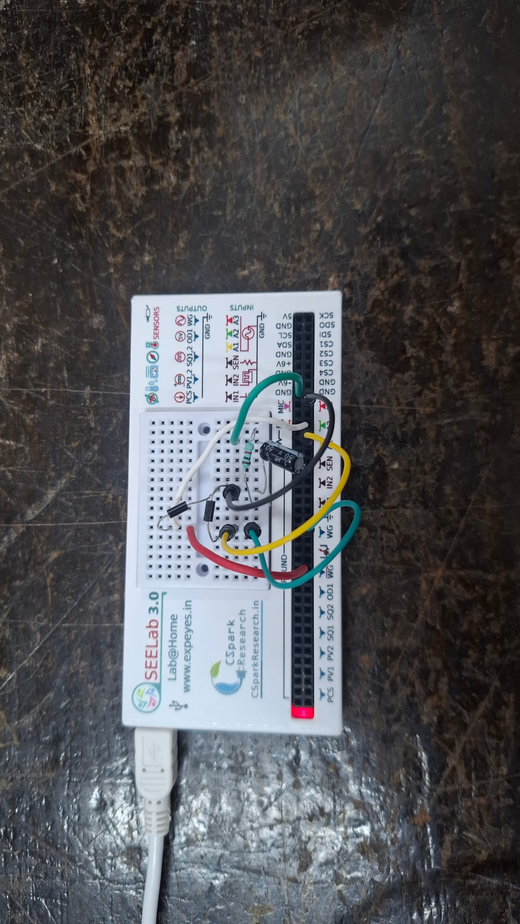
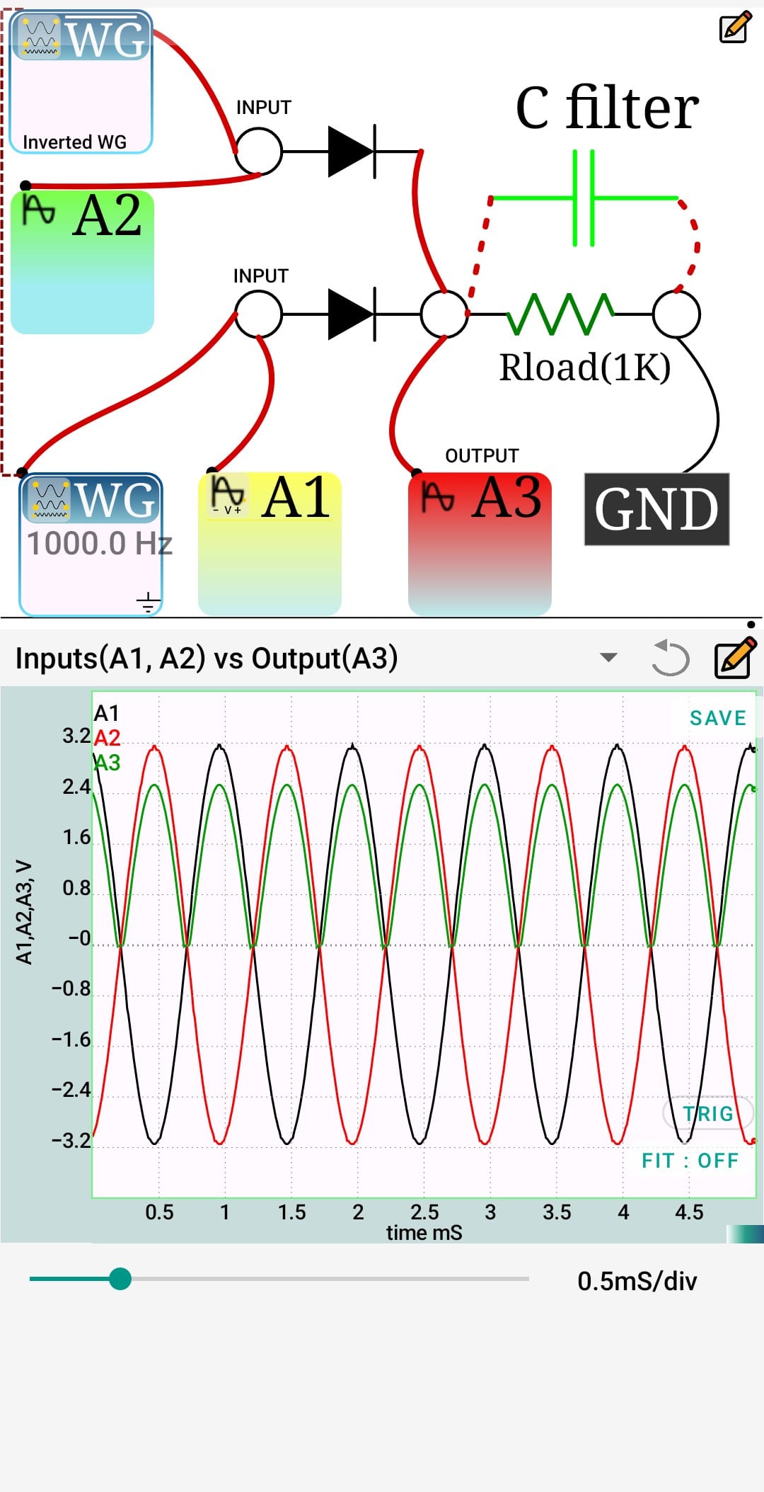
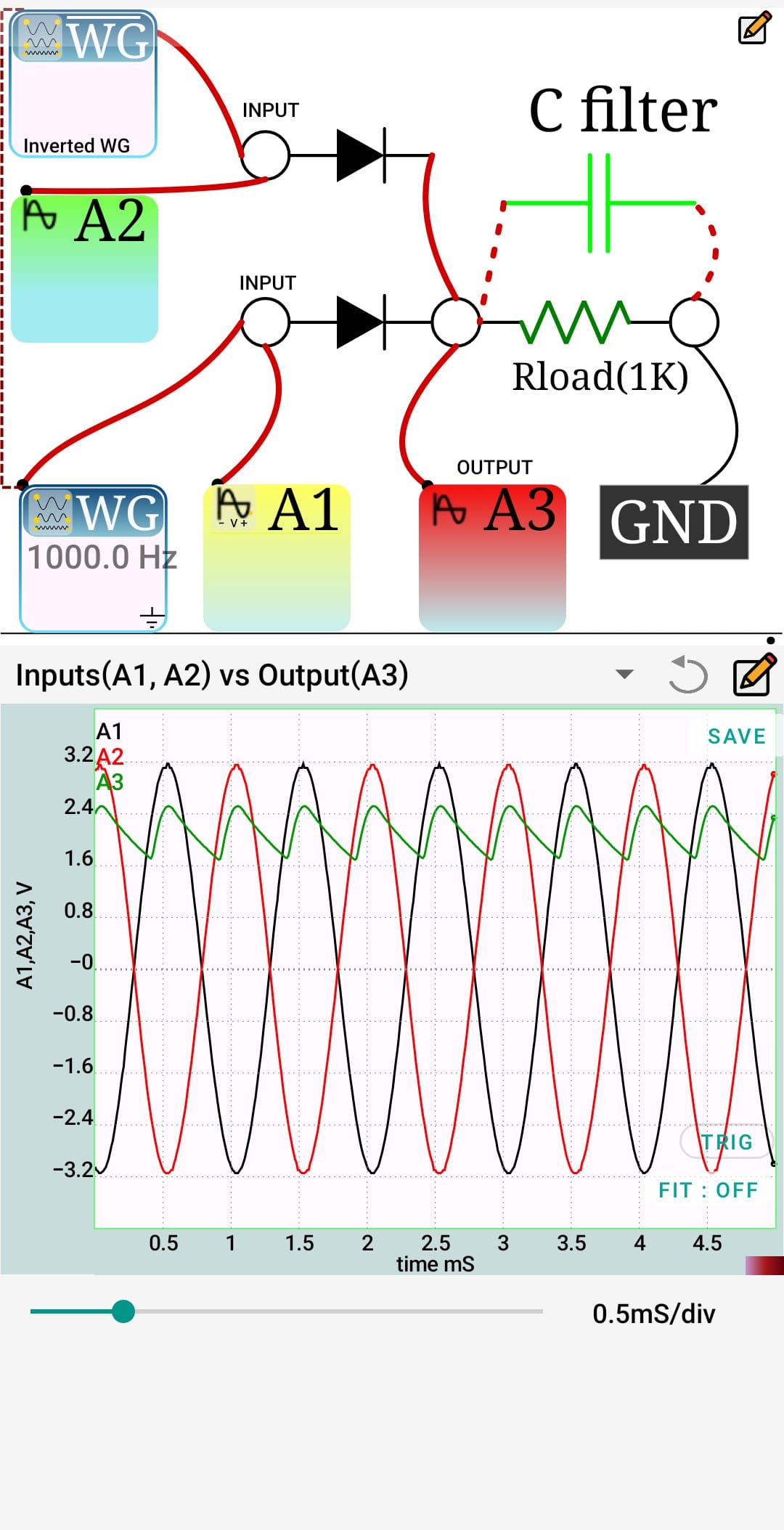
The setup uses SEELab3's WG and its inverted output as two 180°-out-of-phase sources, mimicking a center-tapped transformer secondary. Each feeds a diode, and both diodes join at a common output across a 1K load resistor, with a capacitor filter that can be switched in or out across the load.
Without the filter, A3 clearly shows a full-wave rectified waveform — two humps per input cycle, dropping to zero between them, since each diode conducts only for its own half-cycle. Adding the capacitor across the load smooths this into a waveform that stays mostly high, dipping by only about 0.8V as the capacitor discharges through Rload between conduction peaks. This is the classic effect of a reservoir capacitor: it charges to the peak voltage while a diode conducts, then holds the voltage up until the next diode fires.
Half-Wave Rectifier: With and Without a Filter
A single-diode half wave rectifier studied with SEELab3 — first without a filter capacitor, then with one added across the load, to see how the output waveform changes.
Apparatus: SEELab3, breadboard, 1 diode, 1K load resistor, filter capacitor, jumper wires — using SEELab3s WG (1000 Hz) as the input source.
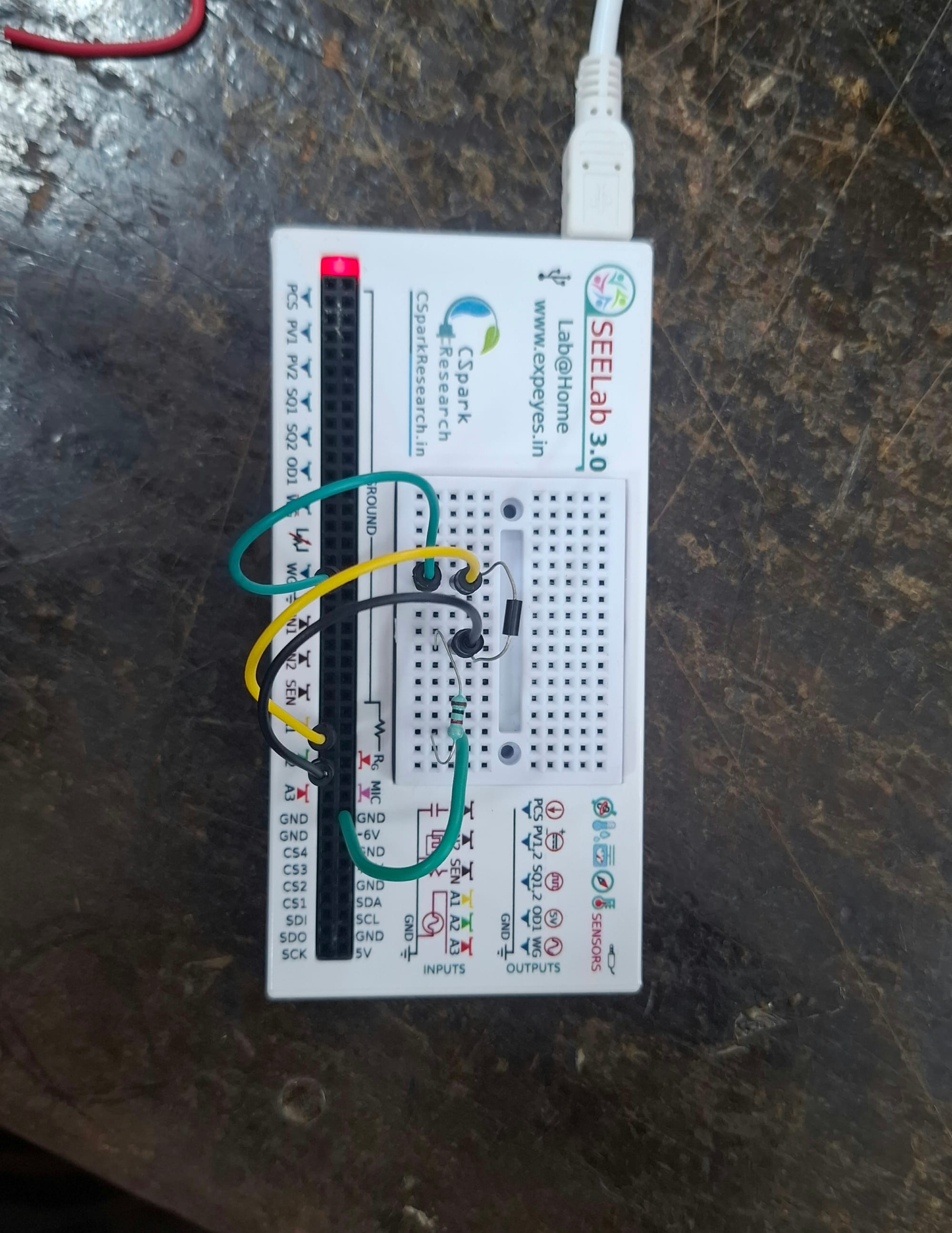
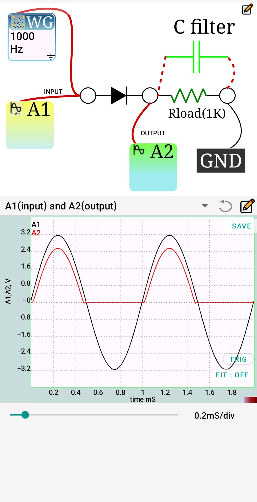
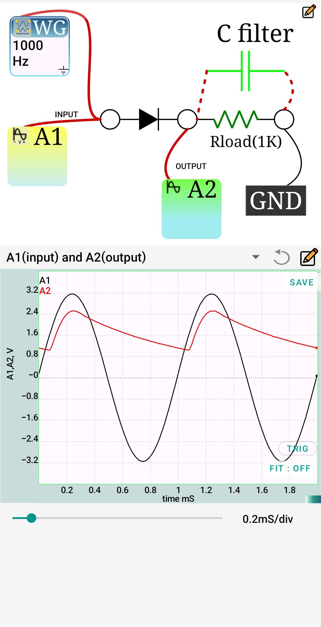
Observation: A single-diode half-wave rectifier was built with a 1K load, driven by the WG at 1000 Hz. Without the filter capacitor, output A2 followed only the positive half of each input cycle — tracking up to about 2.4V (below A1's 3.2V peak due to the diode's forward drop), then flattening at 0V for the entire negative half-cycle since the diode blocks reverse current. Adding the capacitor across the load changed this completely: A2 now charged up to the same ~2.4V peak during conduction, but instead of dropping to zero, it discharged slowly through Rload over the diode's off-half, producing a large ripple of about 1.6V. This ripple is much bigger than in the full-wave case, since here the capacitor has a full half-cycle to discharge instead of just a quarter — showing why full-wave rectification is generally preferred when smoother DC is needed.
More info at: www.expeyes.in
Frequency Response of a Piezo Buzzer
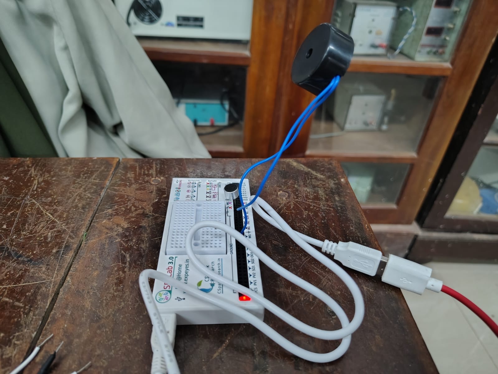
This experiment explores how a piezo buzzer's output changes as the frequency of the input signal is swept across a range, using SEELab 3.0 to generate and vary the driving frequency while recording the buzzer's response. The results show that the buzzer's output peaks sharply near its resonant frequency and falls off as the input moves away from that point in either direction. The experiment gives a practical feel for resonance, frequency response curves, and how piezoelectric transducers like buzzers behave under varying drive conditions.
Verification of Ohm's Law
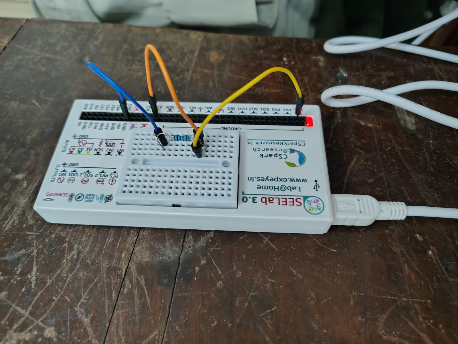
This experiment sets out to confirm the linear relationship between voltage and current in a resistor, using SEELab 3.0 to apply a known voltage across a resistor on the breadboard and record the resulting current at each step. By plotting the measured voltage against current, the data is expected to trace a straight line through the origin, with the slope giving the resistance of the component. The exercise reinforces how Ohm's Law holds for an ohmic resistor and shows how SEELab's built-in sources and measurement channels can be used to characterize a simple circuit element.
Interference of Sound Waves
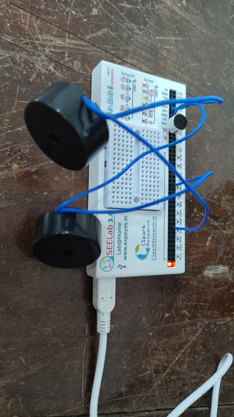
This experiment demonstrates constructive and destructive interference using two identical sound sources driven from SEELab 3.0, with the built-in microphone input used to pick up the combined sound field at different positions between them. As the microphone is moved, the recorded amplitude rises and falls, corresponding to points of constructive interference where the waves reinforce each other and points of destructive interference where they cancel. The experiment gives a hands-on demonstration of superposition and path difference, the same principles behind interference patterns seen in optics and other wave phenomena.
Diode V-I Characteristics
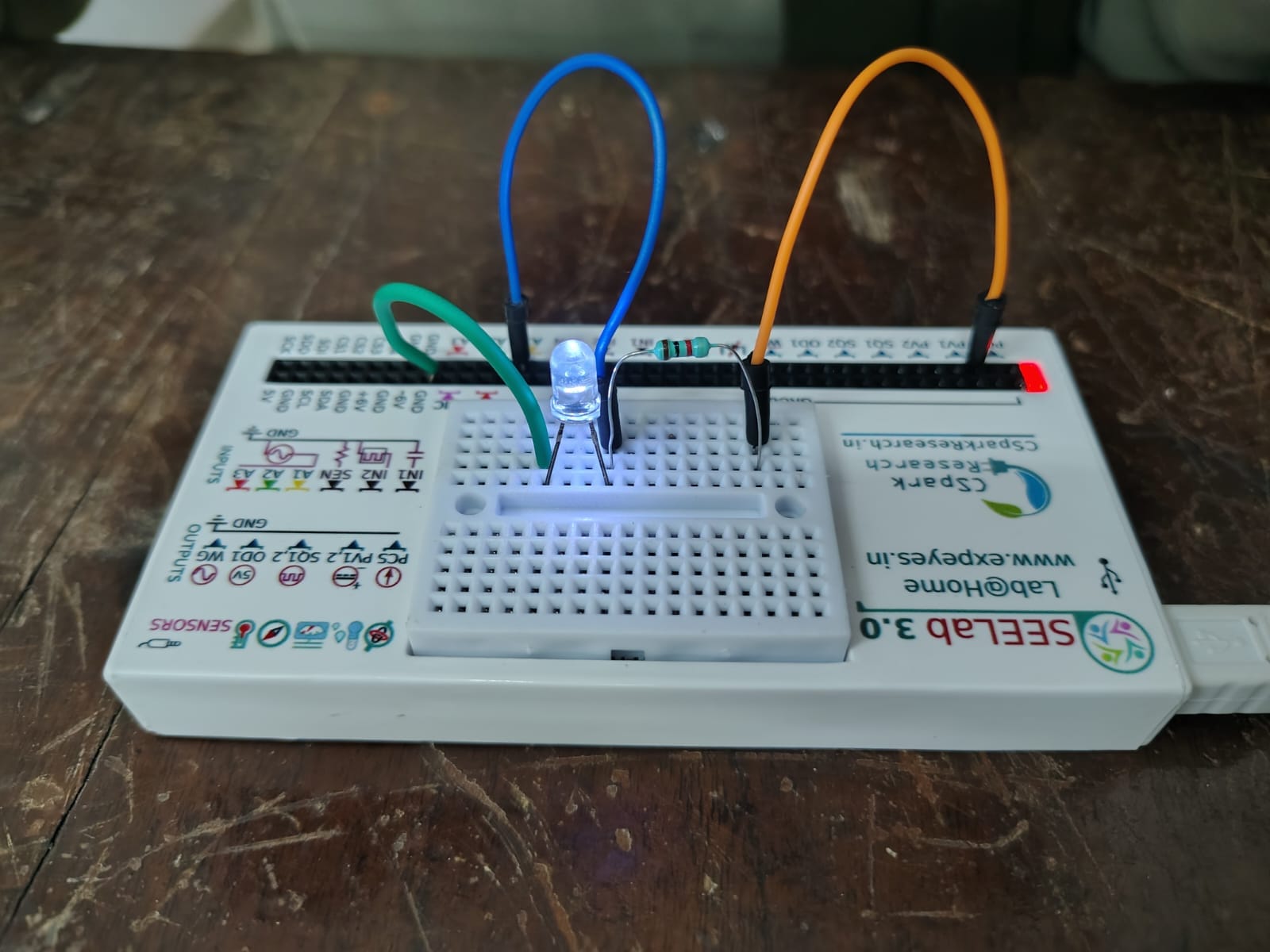
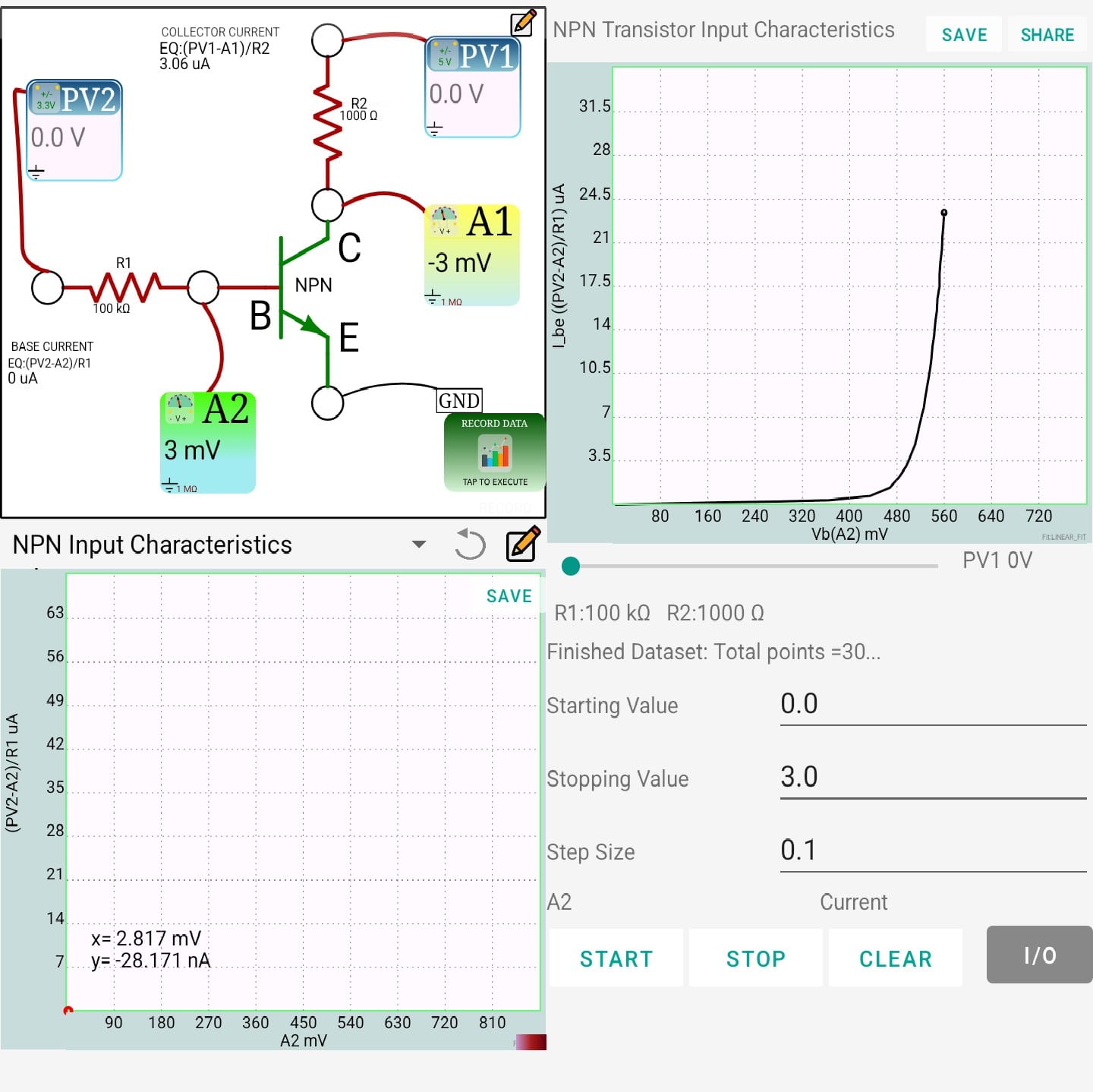
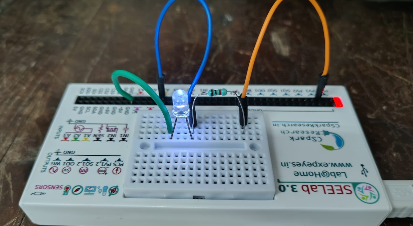
This experiment traces out the voltage-current behaviour of an LED using SEELab 3.0, which sweeps a range of applied voltages across the diode and records the resulting current at each step. The resulting plot is expected to show the characteristic diode curve: almost no current flows until a threshold (turn-on) voltage is reached, after which the current rises sharply with only small increases in voltage. The experiment illustrates the non-linear, one-directional conduction behaviour of a diode and helps identify its forward voltage drop from the measured data.
Clipping Circuit Using Diode
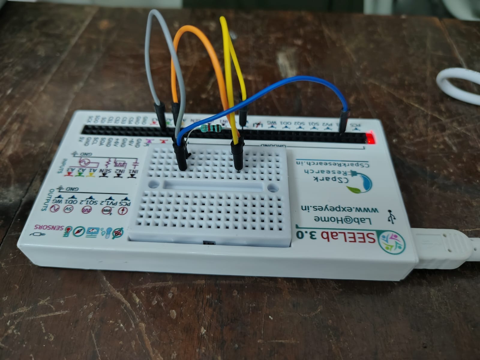
This experiment looks at how a diode can be used to cut off, or "clip," part of a waveform, using SEELab 3.0 to generate a sine wave and observe how a diode and resistor combination reshape it. As the input signal is applied, the diode conducts only when it is forward biased, letting that portion of the waveform pass through largely unchanged while flattening or removing the portion where it stays reverse biased. Comparing the input and output traces shows the clipping level set by the diode's forward voltage, and demonstrates how simple diode circuits are used to limit or reshape signals in practical electronics.
AND Gate Using Diodes
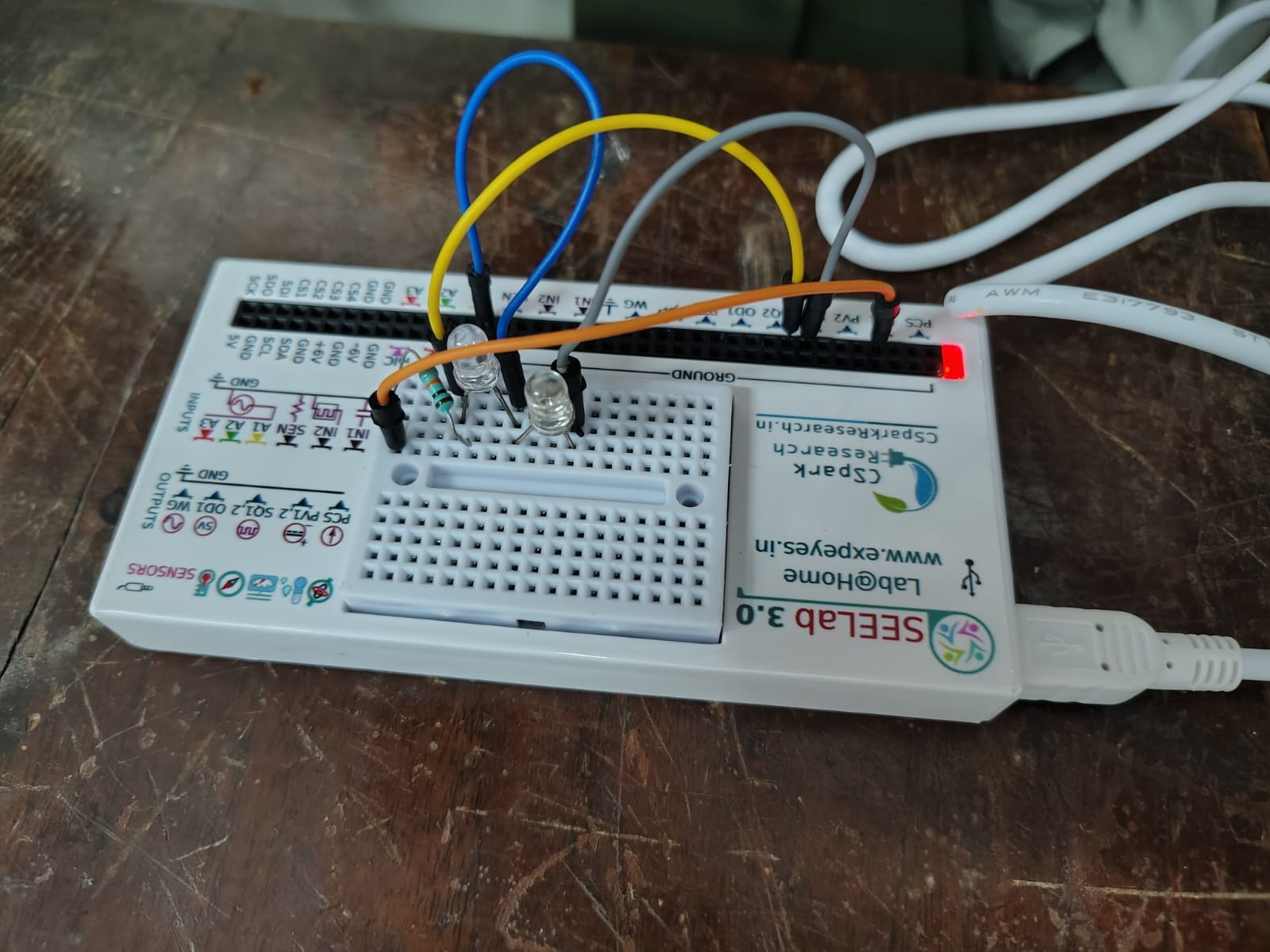
This experiment builds a basic AND logic gate out of two diodes and a resistor, using SEELab 3.0 to apply different combinations of high and low voltage at the two inputs and record the resulting output. Because each diode only conducts when its input is high and the shared output is pulled up through the resistor, the output stays low unless both inputs are high at the same time, at which point it rises to match the input level. Testing all four input combinations and tabulating the output against them reproduces the standard AND truth table, showing how simple diode circuits can implement basic digital logic.
Resistance of the Human Body
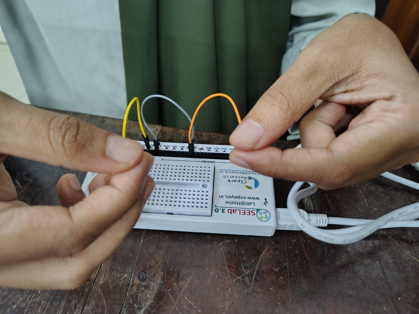
This experiment measures the electrical resistance of the human body using SEELab 3.0, with two leads held one in each hand so that the body itself completes the circuit between a known source and a measuring channel. By applying a small, safe voltage and recording the resulting current, the body's resistance can be calculated and compared across conditions such as dry versus slightly moist skin, or different grip pressures. The exercise illustrates how skin resistance dominates the body's overall resistance and shows how factors like moisture and contact area can cause noticeable variation between individual readings.
𝗗𝗜𝗢𝗗𝗘 𝗖𝗟𝗔𝗠𝗣𝗜𝗡𝗚 𝗘𝗫𝗣𝗘𝗥𝗜𝗠𝗘𝗡𝗧
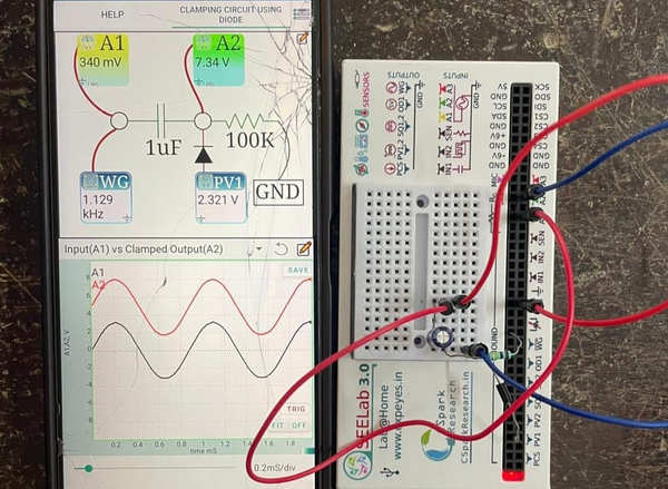
The Diode Clamping experiment demonstrates how a diode and a DC voltage source can shift the average (DC) level of an AC signal without significantly changing its waveform shape. A sine wave from the waveform generator is applied to the clamping circuit, while the PV1 voltage source determines the reference level for the voltage shift.
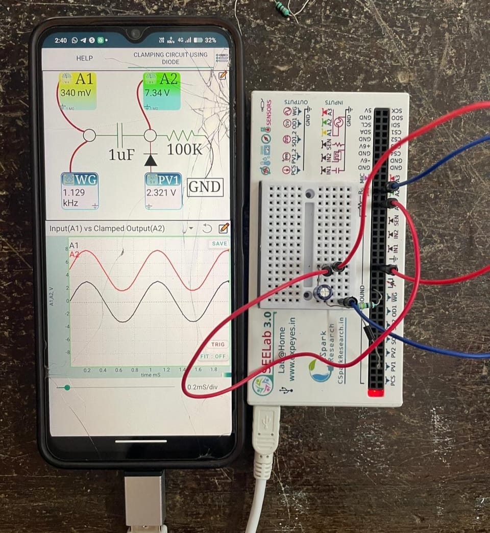
Using ExpEYES/SEELab, the input waveform is observed at A1 and the clamped output waveform at A2. By adjusting the PV1 voltage, the output waveform can be shifted upward or downward. The experiment illustrates the principle of diode clamping and its applications in DC level shifting and electronic signal processing.
Ohm's Law with Alternating Current
This experiment verifies Ohm's Law using alternating current (AC). A known 1 kΩ resistor and an unknown resistor are connected in series, and the RMS voltages are measured using ExpEYES/SEELab. The current is calculated from the voltage drop across the known resistor, allowing the unknown resistance to be determined.
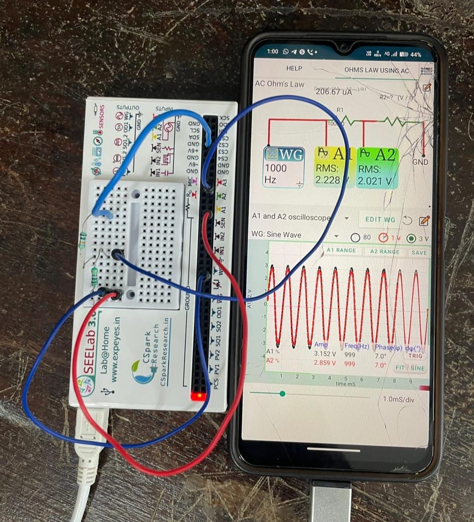
The experiment also introduces the concept of RMS (Root Mean Square) value, which represents the equivalent DC voltage or current that produces the same power as an AC signal. The measured results can be compared with the expected resistor values to verify Ohm's Law for AC circuits.
RC Integrator
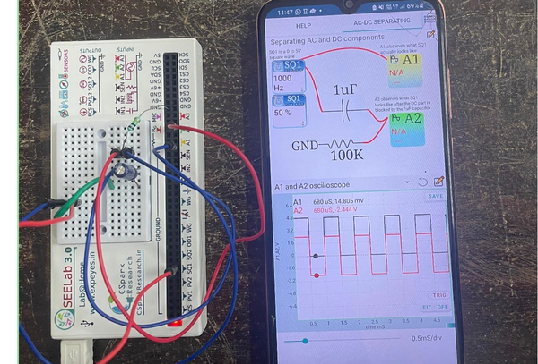
This experiment investigates the operation of an RC integrator circuit using the SEELab 3 (ExpEYES) platform. The circuit consists of a resistor and a capacitor connected in a configuration that produces an output voltage approximately proportional to the time integral of the input voltage. A square-wave signal is applied to the circuit, and the input and output waveforms are observed using the SEELab software.
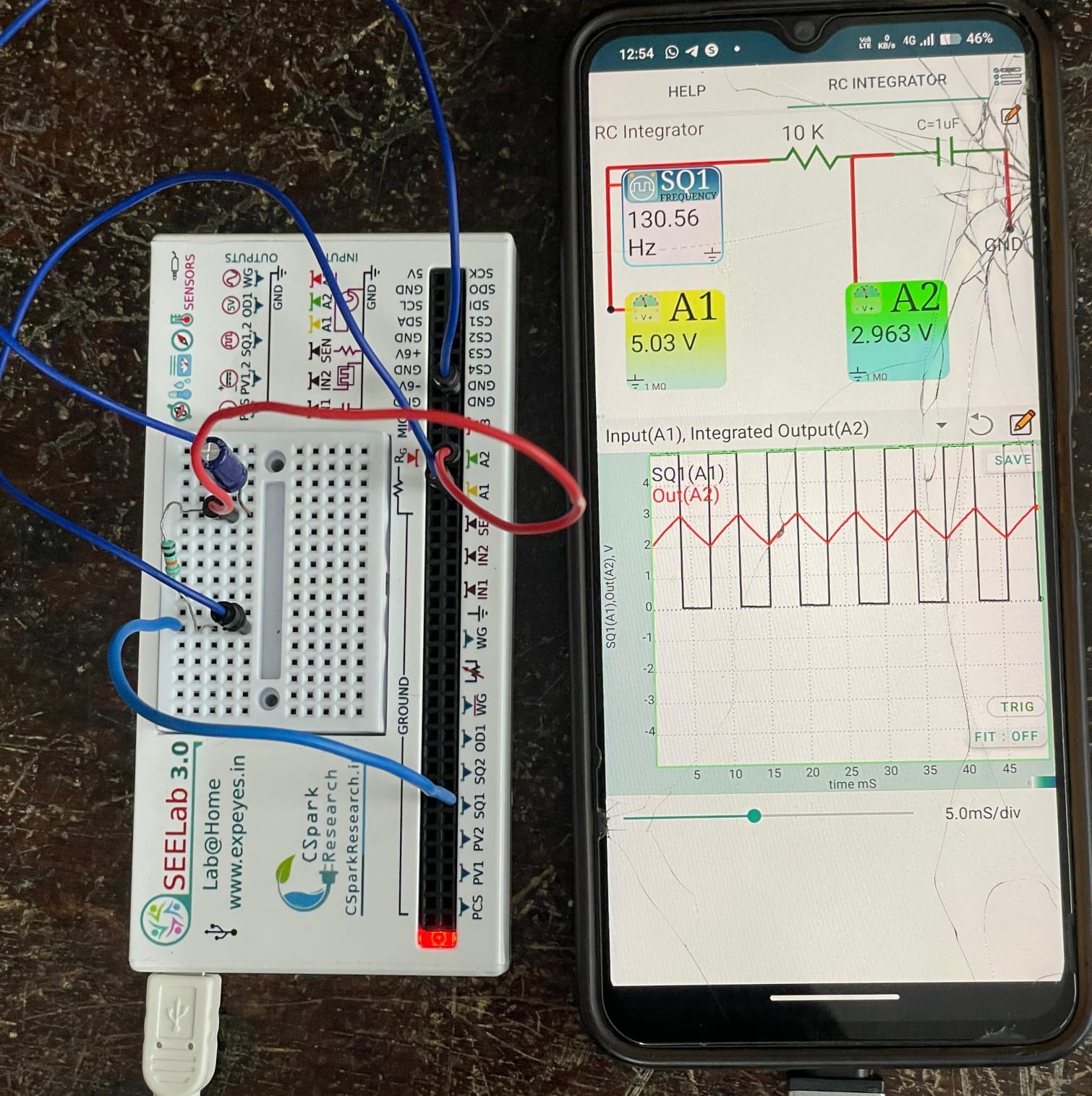
The experiment demonstrates the frequency-dependent behaviour of RC circuits and the principle of signal integration. When the circuit operates under suitable conditions, the square-wave input produces an approximately triangular output waveform. The experiment helps students understand the charging and discharging of capacitors and the practical applications of RC integrators in signal processing and electronic circuits.
𝗗𝗜𝗢𝗗𝗘 𝗖𝗟𝗜𝗣𝗣𝗜𝗡𝗚
The Diode Clipping experiment demonstrates how a diode limits the amplitude of an input signal by clipping portions of the waveform that exceed a specified voltage level. A sine-wave signal is applied to a clipping circuit, and a reference voltage (PV1) is used to set the clipping level. When the input voltage exceeds the reference voltage by approximately the diode's forward voltage drop (about 0.6–0.7 V for a silicon diode such as the 1N4148), the
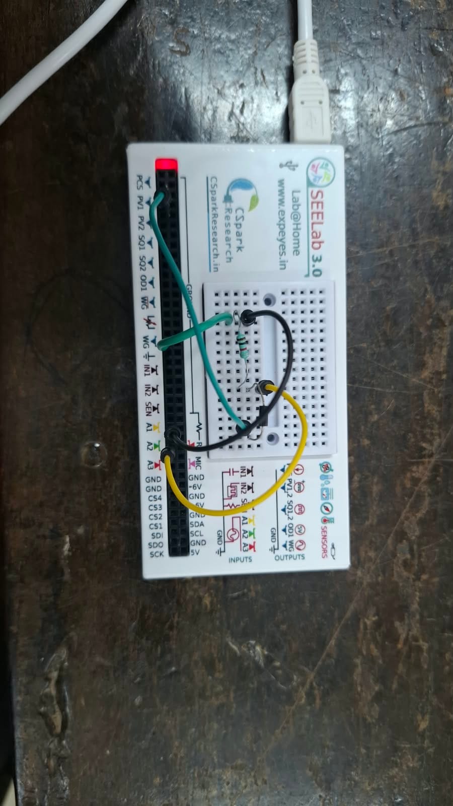
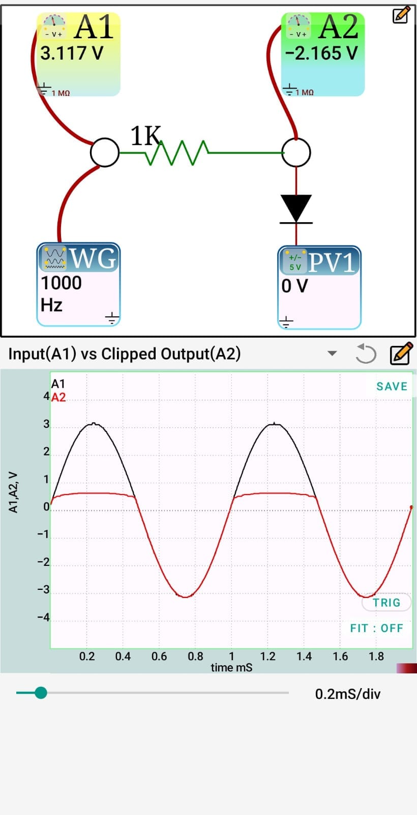
Using the SEELab 3 (ExpEYES) platform, the input and output waveforms can be observed and compared while varying the reference voltage. The experiment demonstrates the operating principle of diode clippers and their applications in waveform shaping, signal limiting, and electronic protection circuits.