8 channel temperature logger with SEELab 3
Details on how to create an 8 channel temperature logger add-on for SEElab3 using thermistors and 2 16-bit ADS1115 ADCs.

Components
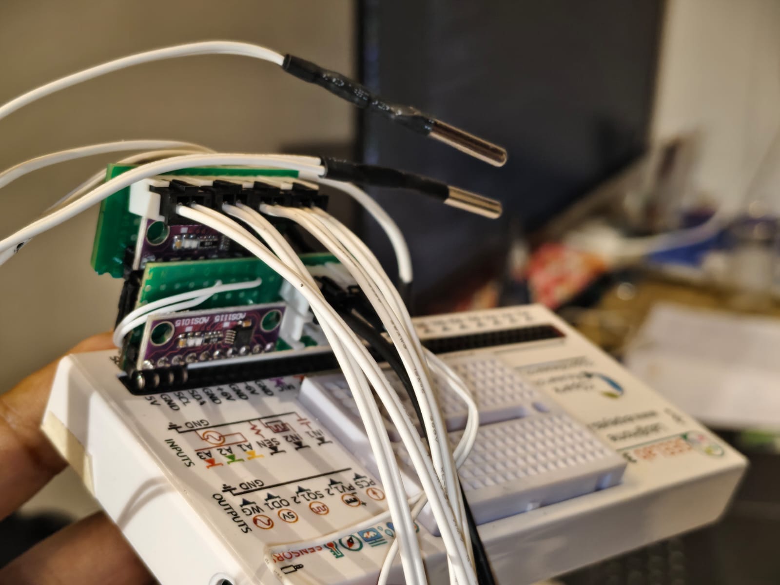
- 2x ADS1115
- 8x 100K NTC Thermistor
- 8x 100K resistor
- 3.3V regulator : XC6206P332MR (662K). Or use PV1 set to 3.3V.
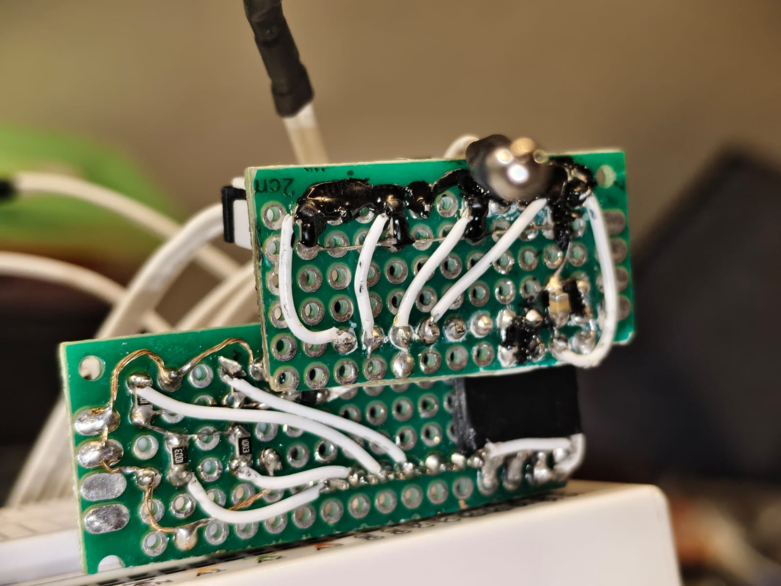
- prototyping board
- wires
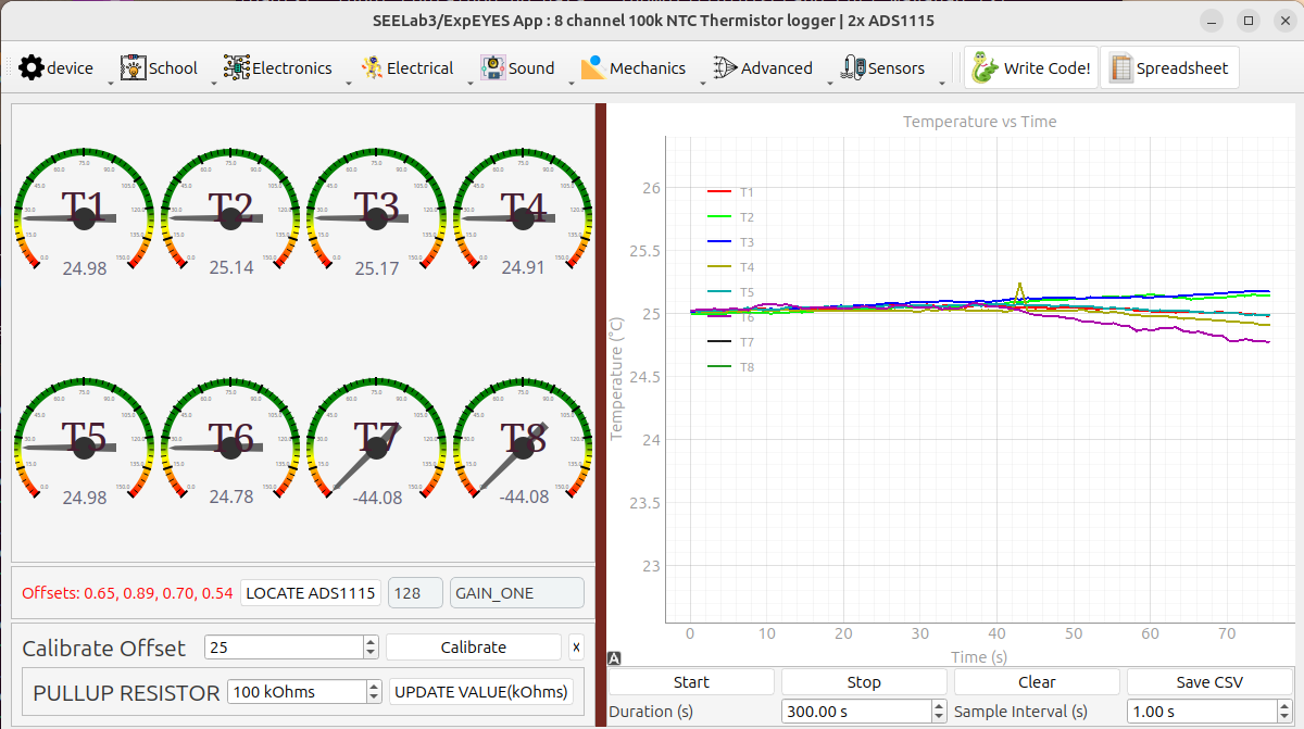
Software Menu : Advanced > 8 Channel Thermistor Logger | 2x ADS1115
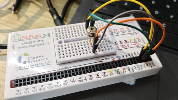
The ADS1115 is a 16-bit ADC with 4 single ended inputs which can measure up to 4 Volts. Each thermistor is pulled up to 3.3V via a 100K resistor, creating a potential divider network. With one end at 3.3V, the other at GND(0 V), the midpoint voltage depends on the resistance of the thermistor which is temperature dependent. at 25C , the thermistor is at 100K, so the midpoint is 1.65 volts. We use an equation to calculate the thermistor resistance based on this midpoint voltage, and then another equation to convert resistance to temperature.
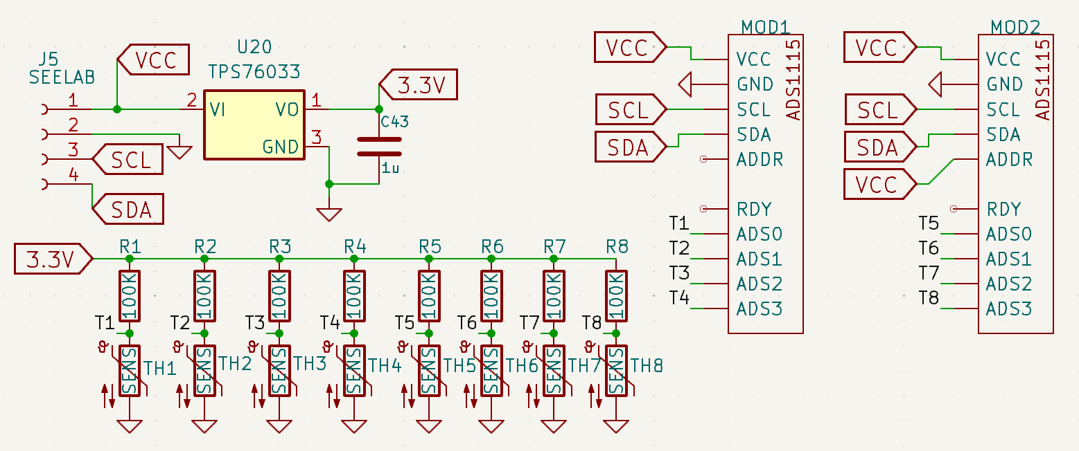
8 such dividers are made , of which 4 midpoints are connected to ADS0 to ADS3 of one ADS1115, and the next four to another ADS1115 . The SCL and SDA lines of both are connected in parallel to seelab's SCL, and SDA, so we must set one of the ADS1115 to have a different communication address. The default address (ADDR pin unconnected or grounded), is 0x48 (72) . If the ADDR pin is connected to VCC(5V), then the address becomes 0x49 (73) . So for one ADC we connect ADDR to VCC.
The software then detects both ADS, and displays readings from all 8 sensors. I have connected only 6, so the last 2 are wrong readings and the graph will not display them when you try to plot data.
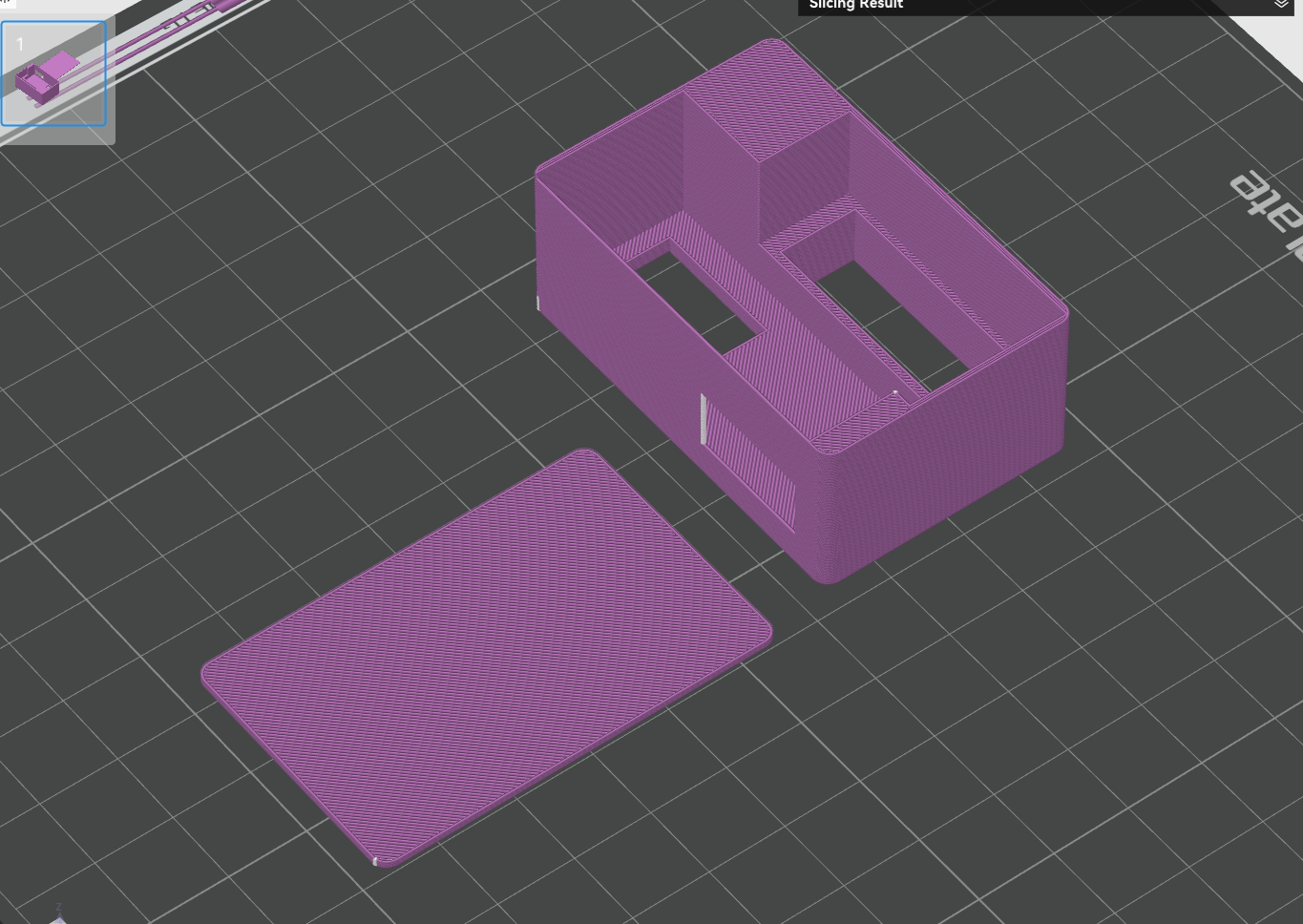
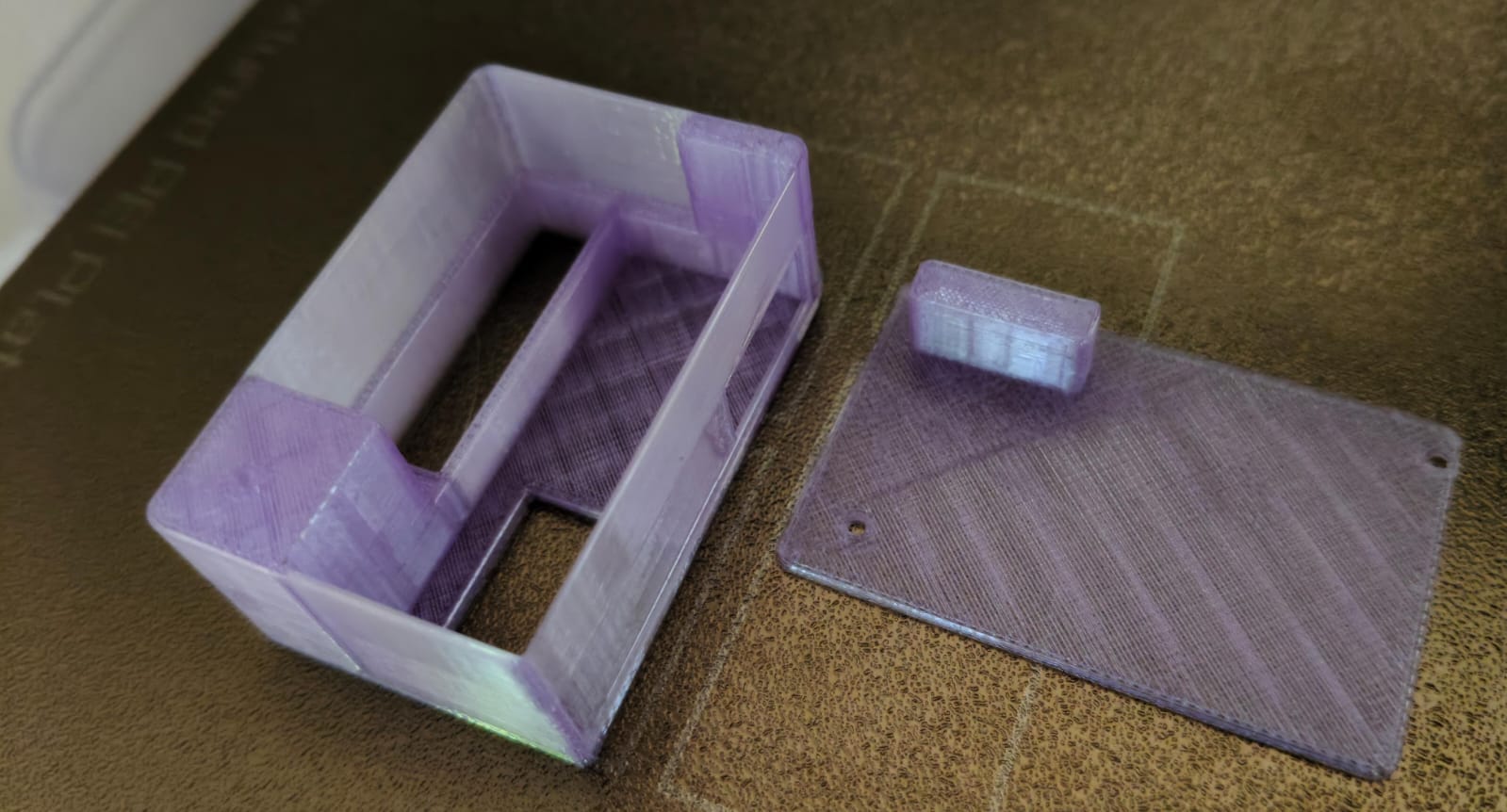
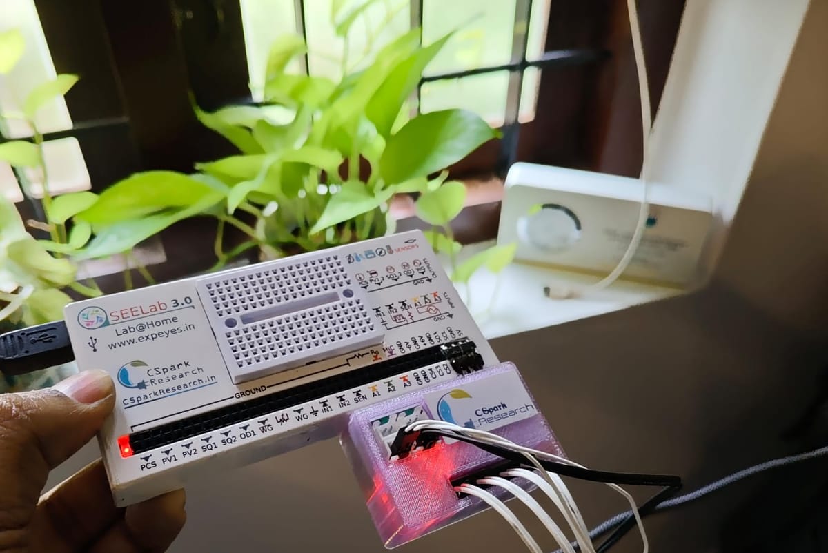
A More snug fitting design
Broke out the vernier callipers to tighten the tolerances and make it better !

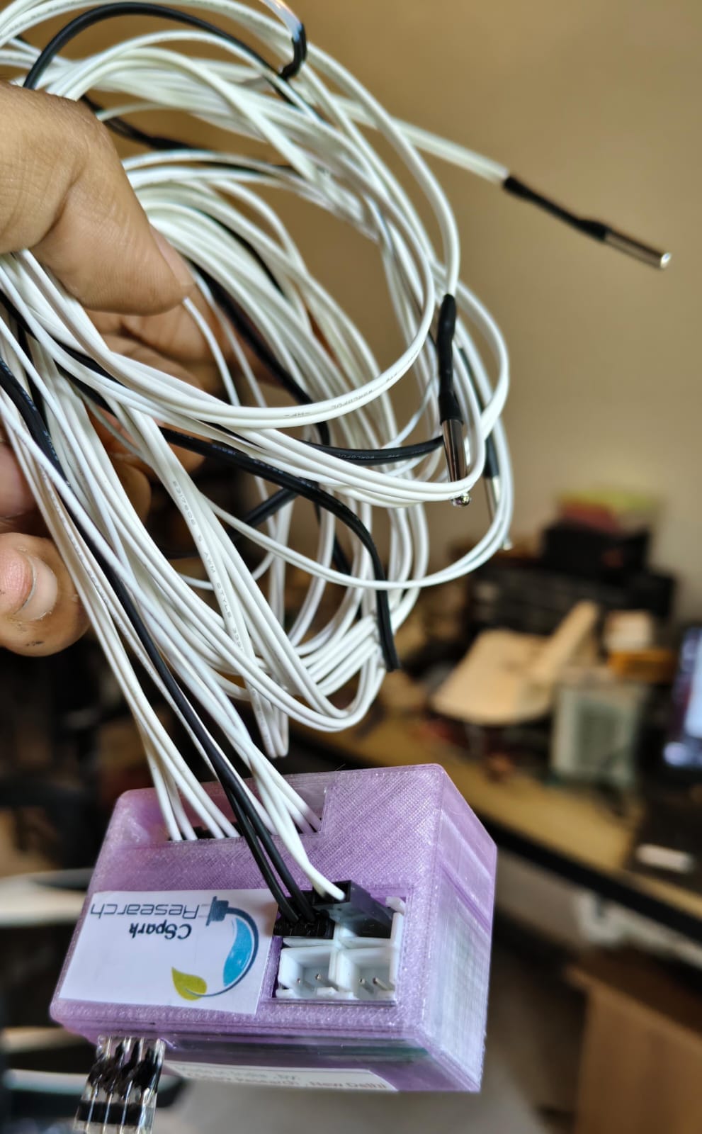
DONE!